Learning Goals: Students will be able to
- Discuss basic electricity relationships in series and parallel circuits
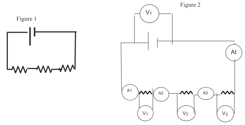
- Build circuits from schematic drawings
- Use voltmeters and ammeters to take readings in circuits.
- Provide reasoning to explain the measurements in circuits.
Construct the circuit figure 1 using The Circuit Construction Kit (CCK) simulation at the PHeT site. Make the resistors have different value and record the value of each resistor. Use the ammeter moving it to take readings in the different places seen in figure 2. Then use the voltmeter to take voltage readings. Calculate R using Ohm’s Law (V=IR) for the total resistance in last column.
| Resistor | Voltage(V) | Current(A) | Resistance(𝝮) |
| 1 | 3.0 | 0.30 | 10 |
| 2 | 3.0 | 0.30 | 10 |
| 3 | 3.0 | 0.30 | 10 |
| Total | 9.0 | 0.30 | 30 |
a. How is the total resistance related to the individual resistances? Total current to the individual currents? Total voltage to the individual voltages?
Total resistance is the sum of the individual resistances. Current is the average of the individual currents. Voltage is the sum of the individual voltages.
b. Write a paragraph explaining what you think is happening in series circuits to cause the above relationships to occur. _(You made a similar circuit with light bulbs using CCK. You may want to experiment with the sim again, keeping in mind that light bulbs are just resistors that glow.)._
All current that flows through a series circuit is constant, meaning the property that must change to allow for multiple resistors is voltage. Wouldn't make sense otherwise, given Ohm's law.
Wire the circuit in figure 1 with the same value resistors that you used in Part 1. Take readings in different places shown in figure 2 by moving the meters. Make a table like the one below, calculating total resistance using Ohm’s Law (V=IR) for the last column.
| Resistor | Voltage(V) | Current(A) | Resistance(𝝮) |
| 1 | 9.0 | 0.9 | 10 |
| 2 | 9.0 | 0.9 | 10 |
| 3 | 9.0 | 0.9 | 10 |
| Total | 9.0 | 2.7 | 3.3333 |
a. How is the total resistance related to the individual resistances? Explain what you think is happening.
The total resistance of the circuit is the average resistor resistance divided by the amount of parallel paths.
b. Look up the mathematical relationship for finding total resistance in a parallel circuit. Show that your data fits the equation.
\begin{align} \frac{1}{R_{eq}} &= \frac{1}{R_1} + \frac{1}{R_2} + \frac{1}{R_3} \\ &= \frac{1}{10} + \frac{1}{10} + \frac{1}{10} \\ &= \frac{3}{10} \Omega^{-1} \\ \frac{3}{10} \Omega^{-1} &= \frac{10}{3} \Omega \\ &= 3.3333333 \Omega \end{align}c. Imagine you and your friends are running in the neighborhood like electrons flowing through a circuit. Make up stories that would serve as analogies for a parallel versus series circuits. Share your stories with another group and see if they make sense.
Let's say that voltage is the amount of people we're able to move, and amperage is the speed at which we can move. Parallel circuits are like several crosswalks across a long, busy street. When a gap in traffic occurs, it's a lot easier for high foot traffic to cross the street. Conversely, a series circuit is like a long path of several crosswalks across several roads. Traffic gaps cannot be reused, so we're less able to move people across each crosswalk.
d. Summarize the similarities and differences between the series and parallel circuits. Include your reasoning about what you think is happening.
Series circuits are less able to carry current and voltage due to all of the resistors being in the way to getting back to the battery. Parallel circuits are much more efficient in regards to this because of the lower resistance that an electron would encounter on the way back to the battery.